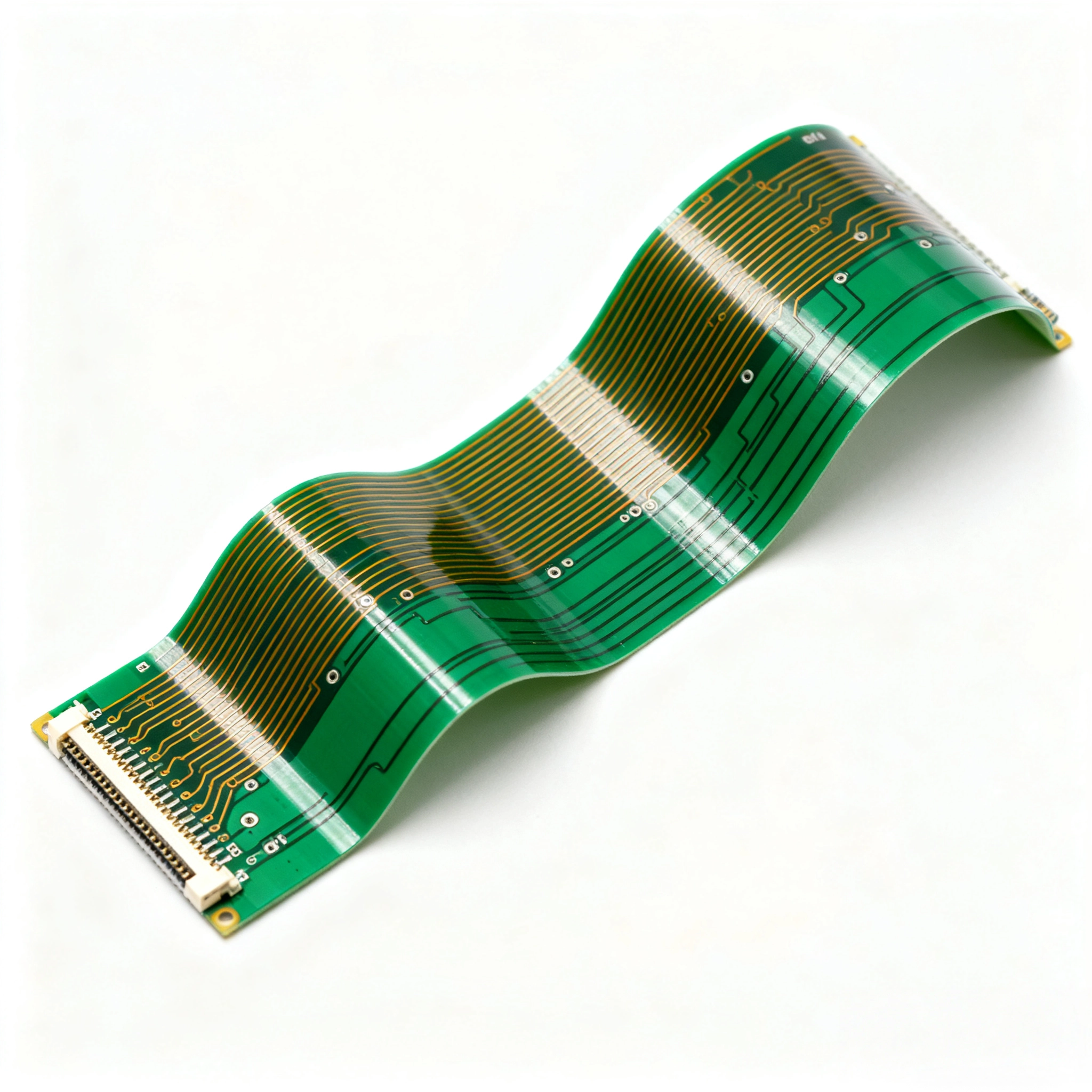
Flexible PCB Boards engineered for space-constrained, highly dynamic bending applications. Supporting 1-20 layers, 0.1mm ultra-thin profiles, and withstanding over 1 million bends. From prototype to mass production in just 7-15 days — accelerate your innovation with stable quality and predictable delivery.
Core Advantages
Extreme Flexibility 360° free bending, folding, rolling. Dynamic flex life >1 million cycles. Ideal for wearables, medical devices, and AI modules.
Lightweight & Space-Saving Thickness 0.1-0.8mm, 60-75% lighter, no extra connectors, 3D routing reduces volume by 40%+.
Extreme Environment Reliability -200°C to +400°C, vibration & chemical resistant. Built for aerospace, automotive ADAS, and industrial control.
Trending Applications
Our Flexible Solutions Serving global clients in aerospace to energy with custom flexible PCB and PCBA solutions since 2007.
Aerospace & Aviation Satellite modules, avionics, high-reliability boards
Medical Electronics Implantable devices, heart monitors, diagnostic equipment
Automotive & AI EV battery systems, ADAS sensors, AI hardware
Consumer Electronics & Communications Smartphones, drones, 5G modules, LED lighting
Industrial Control & Energy Robot controllers, power systems, semiconductor packages
Our Factory's Manufacturing Capabilities
19 years dedicated to PCB manufacturing since 2007, based in Shenzhen with imported equipment and world-class processes. Full turnkey PCBA including PCB layout, assembly, and testing.
1-20 Layer Range
0.1mm Min Thickness
0.05mm Min Trace/Space
1M+ Bend Lifespan
Materials & Processes
• Polyimide (PI) / PET Substrates
• 0.25oz-2oz Rolled Annealed Copper
• HDI / RF / Rigid-Flex / IMPCB Support
• ENIG / OSP / Immersion Gold Surface Finish
Dimensions & Tolerances
• Max Size Up to 4000×240mm (Single Layer)
• Thickness Tolerance ±0.03mm (≤0.3mm)
• Solder Mask Alignment ±0.05mm
• Steel / FR4 Stiffeners Supported
Service Capabilities
• 24-Hour Rapid Prototyping
• Small Batch to Million-Level Production
• One-Stop PCBA: SMT, THT, BGA/QFN, AOI/ICT Testing
• Full Turnkey Sourcing, DFM Reviews, Functional Testing
Production Process - From Design to Delivery in Just 7-15 Days
01 Requirements Discussion - GERBER / Spec Confirmation
02 Engineering Prototyping - 48 Hours First Board
03 Sample Validation - Bend / Electrical / Environmental Testing
04 Mass Production Optimization - Free DFM Report
05 On-Time Delivery - Global Logistics Tracking
Ready to Launch Your Flexible Project?
Contact Us Email: william@bcpcbsz.com. Our engineers will reply with a quote within 2 hours (weekdays).