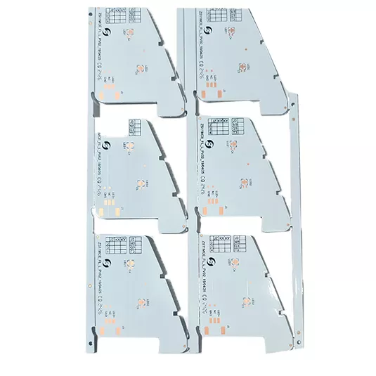
For greater amounts of energy or local thermal loads, e.g in modern constructions with high intensity LEDS, IMS technology can be used. The abbreviation, IMS, stands for “Insulated Metal Substrate.” This is a PCB built on a metal plate – normally aluminium – on which a special prepreg is applied, the primary qualities of which are an excellent capacity for heat dissipation and great dielectric strength against high voltages.
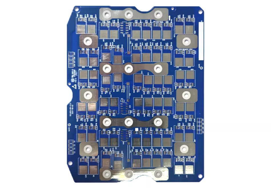
The advantages of IMS PCBs for heat dissipation
An IMS PCB can be designed with a very low thermal resistance. If, for example, you compare a 1.60 mm FR4 PCB to an IMS PCB with a 0.15 mm thermal prepreg, you may well find the thermal resistance is more than 100 times that of the FR4 PCB. In standard FR4 products, it is very difficult to dissipate a large amount of heat away from components.
Feature
Technical Specification
Number of Layers
1-4 layers
Technology Highlights
Effective heat sink solutions for thermal applications. This construction type enables superior heat dissipation through use of either aluminium or copper substrate bonded to the insulated circuitry through thermal pre-preg or resin systems.
Insulated Metal Base PCBs: Thermal Boards for High-Power, High-Reliability Systems
Insulated Metal Base PCBs—also called IMS PCBs or Metal Core PCBs—are built for electronics where heat density is the main design limit. Instead of a fiberglass core, IMS boards use a metal base (aluminum or copper) bonded to a thermally conductive dielectric, with copper circuitry on top. The metal core acts as an internal heat spreader, pulling heat away from hot components and distributing it efficiently into the chassis or heatsink.
For products that must run cool, compact, and stable over long life, IMS is often the most direct upgrade from standard FR-4.
1) IMS vs. FR-4 (Why Metal Base Boards Matter)
Item
IMS / Metal Base PCB
Standard FR-4 PCB
Core
Aluminum or copper base
Glass-epoxy (FR-4)
Heat transfer
Fast, direct spreading through metal
Slower through resin
Best for
High-power / high-temperature circuits
General electronics
Heatsink demand
Often reduced or simplified
Often required for power devices
Lifetime impact
Lower thermal stress, higher stability
Higher thermal stress under load
2) Industries We Serve with IMS PCBs
Different industries demand different thermal and reliability priorities. IMS boards are widely used across your core markets:
Aerospace & Aviation
Used in high-reliability power modules, control electronics, and rugged sensor systems.
RF power stages, base-station modules, high-current DC feeds, and dense telecom power units.
Priorities: stable thermal behavior under sustained load, compact heat paths, predictable assembly fit.
3) IMS Stack-Up (Simple Structure, Big Thermal Gains)
An IMS PCB typically includes three functional layers:
Copper Circuit Layer Carries current and spreads heat laterally. Heavier copper improves current capacity and thermal distribution.
Thermal Dielectric (Insulation) Layer Electrically isolates copper from metal while transferring heat downward. Its thermal conductivity and thickness dominate thermal resistance.
Metal Base Layer Provides stiffness and fast heat spreading into chassis/heatsink. Aluminum balances cost and performance; copper supports extreme heat flux.
4) Core Material Choices (How to Select)
Aluminum Core
Best fit for most high-power designs, including LED systems and automotive/industrial power boards.
Lightweight, cost-efficient, excellent thermal spreading for mainstream needs.
Copper Core
Chosen for aerospace-grade, AI/HPC, and semiconductor equipment where thermal margin is very tight.
Higher thermal conductivity and stiffness, typically higher cost.
Selection tip: Start from power dissipation + allowable junction temperature + mounting approach. Core material should follow the thermal target.
5) What Matters Most in IMS Manufacturing (Industry-Grade Focus)
A good IMS board is not just “metal + insulation.” Reliability across your industries depends on consistent control of:
Thermal dielectric stability Uniform bonding and thickness consistency for predictable heat flow.
Copper-to-dielectric adhesion Prevents delamination under thermal cycling (critical for automotive, AI, industrial, and aerospace).
Heat-and-current copper engineering Copper distribution designed to carry load and spread heat without bottlenecks.
Precision mechanical machining Clean routing, countersinks, slots, and mounting holes for tight chassis/heatsink fit.
Assembly-compatible surface finish Chosen to match your soldering process and reliability expectations.
Thermal reliability validation Screening against thermal shock/cycling, solderability drift, and insulation integrity loss.
6) Thermal-DFM Tips That Improve Performance & Yield
Dielectric choice drives real thermal resistance If hotspots are limiting lifetime, tuning dielectric grade and thickness is the fastest fix.
Copper weight is a thermal + electrical lever Use heavier copper under power devices and high-current paths; avoid over-specing the entire board.
Heat must exit the board cleanly Define flatness, screw torque, thermal pad type, and chassis contact points early.
Avoid narrow thermal bottlenecks Ensure continuous copper under hot components; small pads and thin traces trap heat.
Lock mechanical features early Cutouts, countersinks, and special outlines affect machining route and cost.
7) Major Cost Drivers (What Changes Price Fast)
Aluminum vs copper core selection
Thermal dielectric grade choice
Copper weight and any heavy-copper zones
Outline complexity and special machining
Surface finish type
Single/double-layer IMS vs multi-layer IMS
A focused DFM review often reduces cost without sacrificing thermal targets.
8) RFQ Checklist (Send This for a Fast, Accurate Quote)
RFQ Item
What to provide
Why it matters
Design files
Gerber or ODB++
Confirms routing, copper areas, outline
Thermal targets
Power map, max junction temp, target thermal resistance
Determines dielectric/core strategy
Stack-up intent
Core material preference, copper weights, insulation needs
IMS boards are a proven way to raise power density while keeping devices cool, compact, and stable across long duty cycles. If your application is in aerospace, AI computing, automotive power, semiconductor equipment, medical electronics, industrial drives, or communications hardware, send your Gerber + thermal targets (power dissipation and allowable temperature window). We’ll return a quick thermal-DFM review and a practical quotation based on your real heat-management goals.