
Automotive electronics is one of the core application scenarios for PCB (Printed Circuit Board) technology. As automobiles evolve toward electrification, intelligence, and connectivity, different types of PCBs—flexible FPCs, rigid PCBs, and rigid-flex PCBs—leverage their differentiated characteristics to complement and synergize with each other in in-vehicle electronic systems. This article systematically breaks down the technical advantages, core application scenarios, and supporting value of these three types of PCBs for the upgrading of automotive electronics.
I. Flexible Printed Circuits (FPCs): Adapting to the "Lightweight, Integrated" Needs of Automotive Electronics
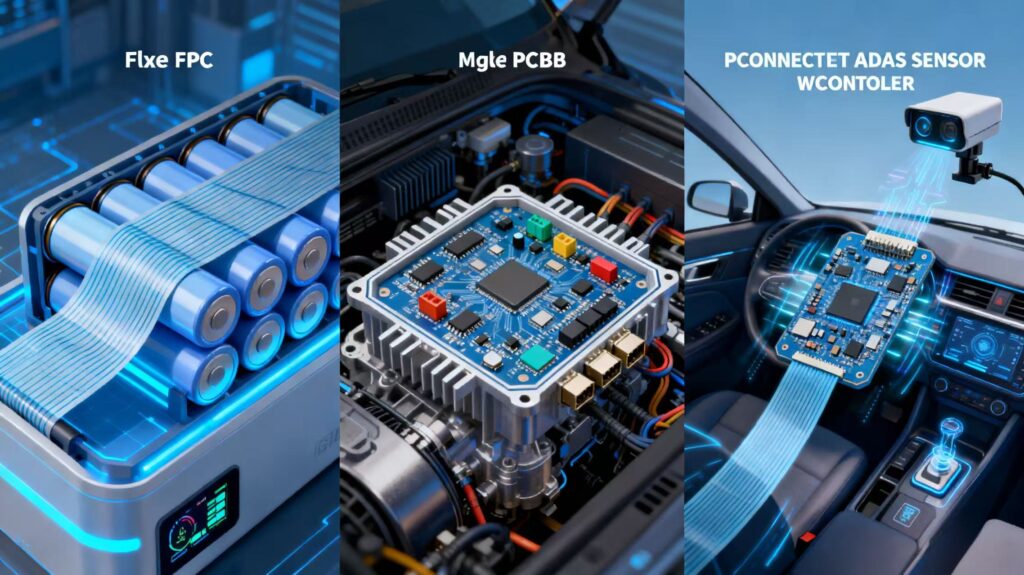
Flexible Printed Circuits (FPCs) use polyimide (PI) or polyester film as the base material. They feature bendability, thinness, and high-density wiring, enabling complex circuit connections in limited spaces. Perfectly matching the core needs of automotive electronics—"weight reduction, space saving, and adaptation to irregular structures"—FPCs have become key components in new energy vehicles and smart cockpits.
1. Core Technical Advantages
- Spatial Adaptability: With a thickness as thin as 0.1mm, FPCs can be folded and bent at angles up to 180°. They can fit on curved vehicle surfaces (e.g., inside battery packs, instrument panels) or in narrow gaps (e.g., between sensors and ECUs), solving the problems of "wiring congestion and space waste" associated with traditional wires.
- Lightweight and Reliability: Compared with traditional wire harnesses, FPCs are 30%-50% lighter (calculated by unit length) and eliminate the risk of loose wire connectors. In environments with vehicle vibration and jolting (e.g., near the chassis or engine compartment), the stability of signal transmission is improved by over 40%.
- High-Density Integration: Supporting fine circuits (line width/line spacing down to 20/20μm) and multi-layer designs (commonly 4-8 layers), FPCs can integrate passive components (resistors, capacitors) and connectors, reducing the number of solder joints between components and lowering the probability of failures.
2. Key Application Scenarios and Value
(1) Battery Management Systems (BMS): The "Battery Guardian" of New Energy Vehicles
The power battery pack of a new energy vehicle consists of dozens to hundreds of battery cells. The BMS needs to real-time monitor parameters such as voltage, current, and temperature of each cell (with precision requirements of ±0.1V/±1A/±1℃) and control the balance of charging and discharging. Leveraging its "flexibility + high-density wiring" characteristics, FPCs can be directly attached to the surface of battery cells or module brackets to achieve:
- Multi-channel data collection: A single FPC can connect 12-24 battery cells simultaneously, reducing the number of interfaces of traditional wire harnesses (from over 30 to 5-8) and lowering the risk of heat generation caused by contact resistance.
- Vibration Resistance and Temperature Tolerance: Using high-temperature-resistant PI base material (long-term temperature resistance of -40℃~125℃), FPCs can operate stably in battery packs (working temperature of -20℃~60℃), avoiding line aging caused by high temperatures.Typical Case: The BMS of Tesla Model 3 adopts 8-layer FPCs to realize synchronous monitoring of over 100 battery cells, improving the battery energy utilization rate by 5%-8%.
(2) Autonomous Driving Systems (ADAS/L4-Level Autonomous Driving): The "Precise Channel" for Signal Transmission
Autonomous driving systems rely on the collaboration of components such as lidar, millimeter-wave radar, cameras (up to 12-15 units), and domain controllers, requiring signal transmission and data processing to be completed within milliseconds. The core value of FPCs is reflected in:
- Wiring in Limited Space: Inside lidar probes (with a diameter of only 5-10cm), FPCs can be bent to adapt to the connection between optical components and signal processing chips, avoiding signal interference caused by wire tangling.
- High-Speed Signal Support: Using low-loss base materials (e.g., modified PI with dielectric loss Df ≤ 0.002), FPCs can transmit high-speed signals of over 10Gbps, meeting the real-time data transmission needs of 4D millimeter-wave radar (with a resolution of 0.1°).
(3) Smart Cockpits and Body Control: The "Invisible Link" Enhancing User Experience
- Smart Cockpits: FPCs connect central control screens, instrument panels, HUDs (Head-Up Displays), and seat control modules, supporting high-definition images (4K/8K) and synchronous transmission of multiple commands (e.g., the linkage of seat heating + massage + electric adjustment). The wiring space is reduced by 60% compared with traditional wire harnesses.
- Body Detail Control: In movable components such as folding rearview mirrors and electric tailgates, FPCs can bend 360° with the movement of components (with a fatigue life of over 100,000 times), avoiding the risk of wire breakage and improving reliability by 3 times compared with traditional wire harnesses.
II. Rigid PCBs: The Fundamental Support for "High Stability and High Reliability" in Automotive Electronics
Rigid PCBs (Rigid Printed Circuits) use glass fiber-reinforced epoxy resin (FR-4) as the base material. They possess high strength, high mechanical stability, and impact resistance. In "high-load, high-risk" core systems of automotive electronics (e.g., engines, safety devices), rigid PCBs remain irreplaceable core components, accounting for approximately 55%-60% of the total automotive PCB market.
1. Core Technical Advantages
- Mechanical Strength and Anti-Interference: With high substrate hardness (Young's modulus of approximately 20GPa), rigid PCBs can withstand engine vibration (amplitude ≤ 2mm), high temperatures (above 150℃), and chemical corrosion (e.g., engine oil, coolant). Additionally, the metal shielding layer design can effectively isolate electromagnetic interference (EMI).
- Cost and Mass Production Advantages: With mature production processes (etching and drilling yield ≥ 99%), the unit area cost of rigid PCBs is only 1/3-1/5 that of FPCs, making them suitable for the "million-level mass production" needs of automotive electronics.
- High Power Bearing Capacity: Supporting thick copper designs (copper foil thickness of 105μm~210μm), rigid PCBs can carry large currents (e.g., over 20A), meeting the power supply needs of high-power components (e.g., engine ECUs, motor controllers).
2. Key Application Scenarios and Value
(1) Engine Control Systems (ECU): The "Control Center" of the Automotive "Heart"
The engine ECU needs to precisely control parameters such as fuel injection, ignition timing, and air intake (with control precision of ±0.1ms), imposing extremely high requirements on the stability and environmental resistance of PCBs. The role of rigid PCBs is:
- Physical Support and Heat Dissipation: Adopting an FR-4 substrate + metal heat sink design, rigid PCBs can reduce the working temperature of the ECU (usually 80℃~120℃) by 10-15℃, avoiding chip performance degradation caused by high temperatures.
- High-Power Power Supply: Thick copper circuits (105μm) can carry 15-20A currents, providing stable power supply for actuators such as fuel injectors and ignition coils, and avoiding engine idling instability caused by current fluctuations.
(2) Safety Systems: The "Last Line of Defense" Guarding Driver and Passenger Safety
Automotive safety systems (e.g., airbags, ABS anti-lock braking, ESP electronic stability program) need to trigger without failure in emergency situations (response time ≤ 100ms), and the high reliability of rigid PCBs is the core guarantee:
- Airbag Control Unit (ACU): Adopting 6-10 layer rigid PCBs, it integrates acceleration sensors, MCUs, and driver chips. The line spacing is ≥ 0.2mm (to prevent short circuits), and it has passed the ISO 26262 functional safety certification (ASIL-D level, the highest safety level), ensuring that the airbag deploys normally 100% of the time in collisions.
- ABS System: In the brake hydraulic control module, rigid PCBs can withstand the corrosion of brake fluid (temperature of -40℃~150℃) and meet the strict vibration resistance requirements (frequency of 20-2000Hz) of the automotive chassis, avoiding brake failure caused by signal interruption.
(3) Body Control Module (BCM): The "Housekeeper" of Automotive Electronics
The BCM is responsible for managing dozens of body electrical devices such as windows, door locks, lights, and wipers, and needs to process multiple control commands simultaneously (e.g., automatic window lifting + door lock unlocking + headlight switching). Rigid PCBs provide stable support for this:
- Multi-Functional Integration: A single 4-6 layer rigid PCB can integrate MCU, relay drivers, and communication interfaces (CAN/LIN bus), reducing the number of discrete components by 30% and simplifying the module structure.
- Low Maintenance Cost: With a service life of over 10 years (matching the vehicle's service life), rigid PCBs reduce the maintenance frequency of the BCM. The failure rate is only 0.5%-1%, far lower than the 3%-5% failure rate of FPCs in high-load scenarios.
III. Rigid-Flex PCBs: The "Integrated Solution" for Complex Automotive Electronic Requirements
Rigid-Flex PCBs (Hybrid PCBs) combine the flexibility of FPCs and the mechanical stability of rigid PCBs. They can realize "fixed installation + flexible connection" in a single board, perfectly solving the pain points of "space constraints, high integration, and multi-scenario adaptation" in advanced automotive electronic systems (e.g., high-end ADAS, new energy vehicle powertrains). Their market share in automotive PCBs is rapidly increasing, from 5% in 2020 to over 12% in 2024.
1. Core Technical Advantages
- Structural Integration: The rigid part of the board provides mechanical support for chips and heavy components (e.g., capacitors), while the flexible part realizes bending connection between different modules. This reduces the number of connectors and wire harnesses by 40%-50%, and the overall module volume is reduced by 20%-30%.
- Signal Integrity Optimization: By optimizing the wiring path (integrating rigid and flexible layers into a single board), rigid-flex PCBs avoid signal loss caused by connector contact, reducing signal delay by 15%-25% and improving the anti-interference ability of the system.
- Environmental Adaptability: The flexible part uses high-temperature-resistant PI material, and the rigid part uses FR-4 material, enabling the board to adapt to multiple working environments of the vehicle (e.g., the high temperature of the engine compartment and the low temperature of the chassis) at the same time, with a wide temperature resistance range of -55℃~150℃.
2. Key Application Scenarios and Value
(1) Advanced Driver Assistance Systems (ADAS) Domain Controllers
High-end ADAS domain controllers (supporting L3/L4 autonomous driving) need to integrate laser radar, camera, and millimeter-wave radar data (with a data throughput of over 100GB/s) and complete real-time processing. Rigid-Flex PCBs play a core role here:
- High-Density Signal Transmission: The rigid part of the board carries high-performance chips (e.g., NVIDIA Orin/Xavier), and the flexible part connects to the radar/camera interface. The 8-12 layer design supports PCIe 5.0 (128GB/s bandwidth) and Ethernet 10Gbps, ensuring no loss in high-speed data transmission.
- Space Saving: In the limited space of the vehicle roof (where the ADAS domain controller is usually installed), the flexible part of the rigid-flex PCB can be bent to fit the roof curve, avoiding the problem of "unable to install due to space constraints" with pure rigid PCBs.
(2) New Energy Vehicle Powertrain Systems
The powertrain system (including motor controller, OBC on-board charger, and DC-DC converter) of new energy vehicles has complex structures and high integration requirements. Rigid-Flex PCBs realize:
- Integration of Power and Signal Circuits: The rigid part of the board carries high-power components (e.g., IGBT modules) and uses thick copper (210μm) to withstand 50A+ currents; the flexible part connects the signal detection circuit (e.g., current sensor), avoiding interference between power and signal lines.
- Vibration Resistance in Dynamic Scenarios: In the powertrain (which vibrates violently during vehicle operation), the flexible part of the rigid-flex PCB can absorb vibration energy, reducing the stress on the rigid part by 30%-40% and prolonging the service life of the module.
(3) In-Vehicle Infotainment (IVI) Systems
High-end IVI systems (e.g., multi-screen linkage, in-vehicle communication) require the integration of multiple functions such as display, audio, and network. Rigid-Flex PCBs provide an optimized solution:
- Multi-Screen Connection: The rigid part of the board is fixed in the central control host, and the flexible part extends to the instrument panel and rear-seat display, realizing seamless connection of 3-5 screens without using external wire harnesses.
- Cost Control: By integrating multiple sub-boards into a single rigid-flex PCB, the R&D cycle of the IVI system is shortened by 20%-30%, and the production cost is reduced by 15%-20% (compared with the combination of independent rigid PCBs and FPCs).
Conclusion: The Differentiated Synergy of Three Types of PCBs Drives the Upgrade of Automotive Electronics
In the context of automotive electrification and intelligence, FPCs, rigid PCBs, and rigid-flex PCBs do not replace each other but form a "complementary ecosystem":
- FPCs dominate in "flexible connection, lightweight, and small-space" scenarios (e.g., BMS, smart cockpits);
- Rigid PCBs remain the core in "high-stability, high-power, and mass-production" scenarios (e.g., engine ECUs, safety systems);
- Rigid-Flex PCBs become the key to breaking through technical bottlenecks in "high-integration, complex-structure" scenarios (e.g., ADAS domain controllers, powertrains).


