HomePCB PortfolioIC Substrate PCBs

IC Substrate PCBs

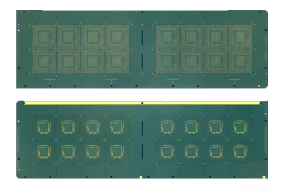
IC Substrate is the chip that makes up the IC bare chip. It is the middle part of the chip package, providing support, heat sink, and protection for the chip, and providing electronic connection between the chip and the PCB. It is a key part in the packaging process, accounting for 35-55% of the packaging process cost.


With the evolution of wafer process technology, the performance requirements for wafer wiring density, transmission rate, signal interference, etc. have increased, which has gradually increased the demand for IC packaging substrates.


SUBFeature
FC-CS2~6 layers
Typical Line Width/Space: 12/12μm - 25μm/25μm
WB-CSP2~6 layers
Package Size: 33mm - 2323mm
Thickness: 0.11mm - 0.56mm
Typical Line Width/Space: 25/25μm - 40μm/40μm
SiPCompatible with BGA, LGA, Flip Chip, Hybrid solutions
Surface Treatment: Soft Au, ENEPIG, ENIG, SOP, OSP
Fine impedance line width control, excellent heat dissipation performance

IC Substrate PCBs: Built for Advanced IC Packaging

IC substrate PCBs (also called packaging substrates) are the high-density interconnect layer between the silicon die and the system PCB. They enable ultra-fine routing, microvia build-up, stable mechanical support, and controlled electrical/thermal performance for modern packages such as FC-BGA, BGA, CSP, and SiP.

If your design is pushing I/O count, bump pitch, thickness, or high-speed performance, the substrate is the foundation that makes the package manufacturable and reliable.


1) IC Substrate vs. Standard PCB (Why It Matters)

ItemIC Substrate PCBStandard System PCB
PositionUnder the die, inside the IC packageMain board for system assembly
PurposeDie-to-board micro-interconnectSystem routing & component assembly
Feature sizeUltra-fine traces/pads/viasLarger features than substrates
Via techLaser microvias + sequential build-upMechanical vias / some HDI
Key risksWarpage, microvia reliability, registrationCost, assembly, SI/thermal balance

What this means for buyers:
You’re not just purchasing a PCB. You’re purchasing a precision packaging platform that decides yield, warpage, and long-term reliability.


2) Typical Applications

IC substrates are widely used in:


3) How to Choose Material & Structure

Material families (choose by performance and assembly):

Structure selection (choose by package goal):

If unsure, send your target package type, bump pitch, and performance goal—we can recommend a DFM-driven stackup.


4) Core Manufacturing Capabilities

Capability AreaWhat matters most
Fine-line build-upMin trace/space for bump-pitch escape
Core featuresStable routing on core layers
Laser microviasDiameter, pad ring, stacked/staggered options
Build-up layers1+N+1 / 2+N+2 / multi-SBU
RegistrationLayer-to-layer alignment window
Warpage controlPackage flatness for assembly yield
Surface finishENIG/ENEPIG/OSP/others per assembly
Reliability validationOpen/short, impedance, thermal cycling, CAF
Traceability & QCFAI, batch trace, process control

Buyer tip:
Ask any supplier for this table. If the limits are unclear, quoting will be guesswork.


5) DFM Tips That Improve Yield & Control Cost

  1. Microvia strategy:
    • Use staggered microvias wherever density allows for better reliability and cost.
    • Reserve stacked microvias for critical high-density zones only.
  2. Keep fine features in stable windows:
    Avoid pushing all critical nets to the absolute minimum line/space unless the routing truly needs it.
  3. Copper balance & symmetric stackups:
    This is the fastest way to reduce warpage, especially for large FC-BGA substrates.
  4. Assembly-driven pad design:
    Match pad geometry and finish to bump/ball pitch and your assembly flow early.

A short DFM review before tape-out usually saves more time than any later optimization.


6) RFQ Checklist (Send This for a Fast, Accurate Quote)

RFQ ItemWhat to provideWhy it’s needed
Design filesGerber or ODB++Confirms routing density & features
StackupDielectric thickness + copper weightsValidates impedance and build-up feasibility
Package typeFC-BGA / BGA / CSP / SiPDetermines structure & finish
Die & bump infoDie size, bump pitch, I/O countChecks escape capability
Reliability targetsIPC class, thermal cycling, temp rangeLocks test plan & material choice
Quantity planPrototype / MPQ / annual volumeOptimizes cost & lead time

Send these once, and you’ll get a practical quote instead of a rough estimate.


7) Typical Project Flow


FAQs

Can a standard PCB replace an IC substrate?
No. Standard PCBs generally cannot meet micro-scale routing density, registration, and warpage control required for IC packages.

Are IC substrates suitable for high-frequency devices?
Yes. With low-loss materials and tight impedance control, substrates are widely used in 5G, RF front-ends, and high-speed compute packages.

Can you help optimize stackup or routing rules?
Yes. Share your target performance and preliminary stackup for a DFM-driven recommendation.


Ready to Start Your IC Substrate Project?

If you’re developing an advanced package and need a substrate partner for fine-line build-up, reliable microvias, and stable mass-production yield, send your Gerber and target stackup for quick DFM feedback and quotation. Early alignment on structure and manufacturability is the shortest path to a stable prototype and smooth scale-up.

Talk to an Expert